 DREAMHILL
DOME PROJECT
DREAMHILL
DOME PROJECT
Central Boiler Energy Saving Modification
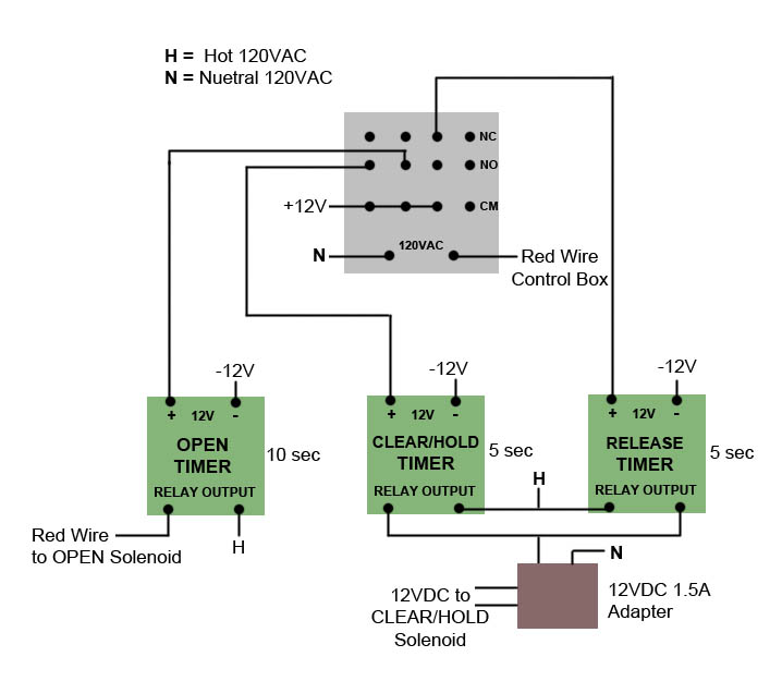
How it works The purpose of this modification is to save 50 watts of needless power consumption by the Central Boiler air damper solenoid which is used to keep the air damper open. The solution is to add a 2nd release solenoid which once the air damper is open, holds it up in place without the need for continous power then the release solenoid can then release it to close. Heres the sequence of how it works: OPEN When the control module presents 120VAC normally routed to the air damper solenoid to open, it is instead used to control the 4PDT relay. The relay activates the OPEN timer and the CLEAR/HOLD timer simultaneously so as the OPEN solenoid pulls the air damper up, the release solenoid is retracted in to clear. The OPEN timer is set for 10 seconds while the CLEAR/HOLD timer is set for 5 seconds so that it holds the OPEN solenoid in the up position. CLOSE When the control module removes the 120VAC then the RELEASE timer is turned on for 5 seconds and the RELEASE solenoid allows the air damper to drop into the closed position.
This results in power consumption for only a matter of seconds rather than months of 50 watts consumption. CAUTION: In the event of power loss the air damper could be held in the up position. If power is not restored the 2 screws on the air damper cover need to be removed and the damper manually released. If power outages are a concern then a simple electronic solution to the above would be a similiar 120VAC relay connected to a small 12V seal ed lead acid battery which releases the RELEASE solenoid using a similiar timer. I'm pretty sure this will void your warranty, but if you are off-grid every watt counts. |
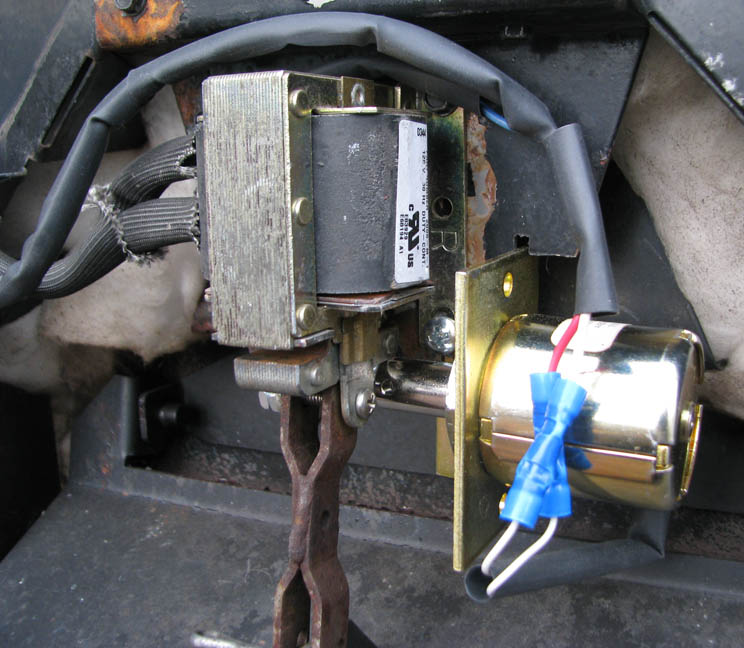
Open position showing RELEASE solenoid plunger holding OPEN solenoid in the up position
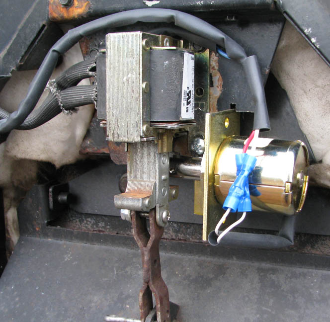
Closed position after RELEASE solenoid allowed gravity to close the air damper
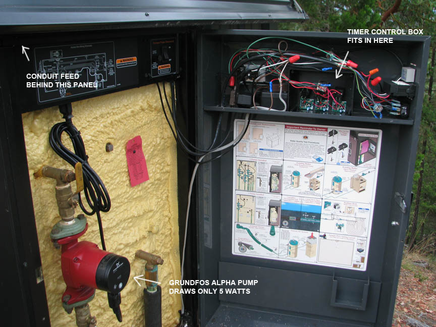
Feeding the 3 wire cable through the conduit to the solenoids using the green ground wire to pull it through
Mounting of components behind the door panel
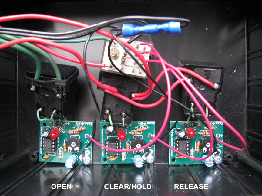
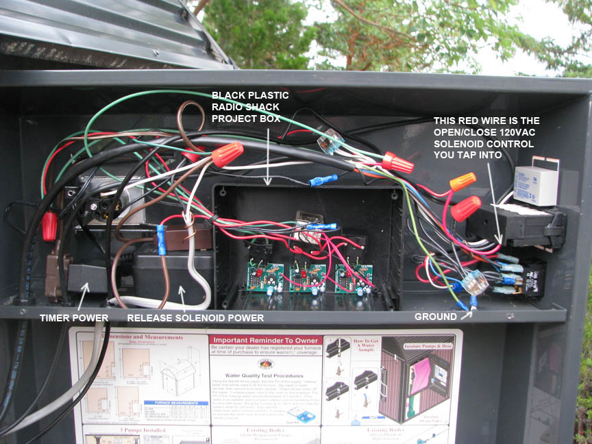
The 3 timers controlled by the 4PDT 120VAC relay which uses the power from the control box red wire
PARTS LIST 12VDC Solenoid $50 Mini Electronic Timer $14 x3 47µF 35V Radial-lead Electrolytic Capacitor $1 x3 12V 120V 20A Relay $3 x3 12V DC/600mA Regulated AC/DC Adapter $13 12V 1500ma Adapter
|
Installation Details You will need to run a 3 condutor cable through the metal conduit in order to deliver power to the release solenoid. Sprinkler wire works and you can use the green ground wire to attach and pull through. You then use 2 of the wires for the release solenoid 12V 1.5A power and the 3rd wire reconnect to the ground lug. The other end of the open solenoid is behind the panel and is the red and white wires. The red wire goes the the control module which is the digital thermostat display. This is the wire you cut and connect the timer control circuitry to. A large black plastic radio shack project box fits in the area easily which houses the 3 timers and control relay. You can tap off the 120VAC hot (black) and nuetral (white) wires in the same area and use cheap extension cords to plug in both the 12V timer power adapter and the large 12V 1.5A release solenoid power adapter. The most complicated part of this install is the mechanically mounting of the release solenoid which has to clear the bottom of the open solenoid and you need to put a bolt and nut to keep the spring from shooting the plunger out. You want to use the smallest spring in the spring kit. I had to remove the 5 screws and take the solenoid assembly apart in order to cut away a section in order to fit this large release solenoid and then use spacer washers to off set it. You want to test the mechanics throughly before you start wiring everything up by using jumper wires to simulate the opening and closing peformed by the timers. You can design your own simple 555 timer circuit and/or substitute components noting required wire gauge sizes and amperage ratings. The parts list is only for reference of the compoents used. If you use the timers from canakit you will need to replace C1 the 470ufd cap with 47ufd to get a better adjustment on the seconds. It's a bit of work, but hey, it's 50 watts saved during the low solar output winter months.
|